FCT Test in PCBA Manufacturing: What It Is and How It Works
Release time:11/06/2026
Share to:
1. What Is FCT (Functional Circuit Test)?
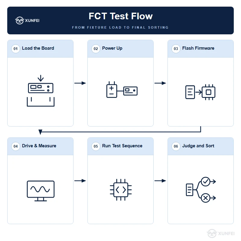
FCT stands for Functional Circuit Test, also called Functional Test (FT). An operator loads the fully assembled PCBA into a test fixture. The station then powers the board up and feeds it the same signals it would see in the field. The board runs its real firmware and performs its real functions. Finally, the test system compares the measured outputs with the product specification.
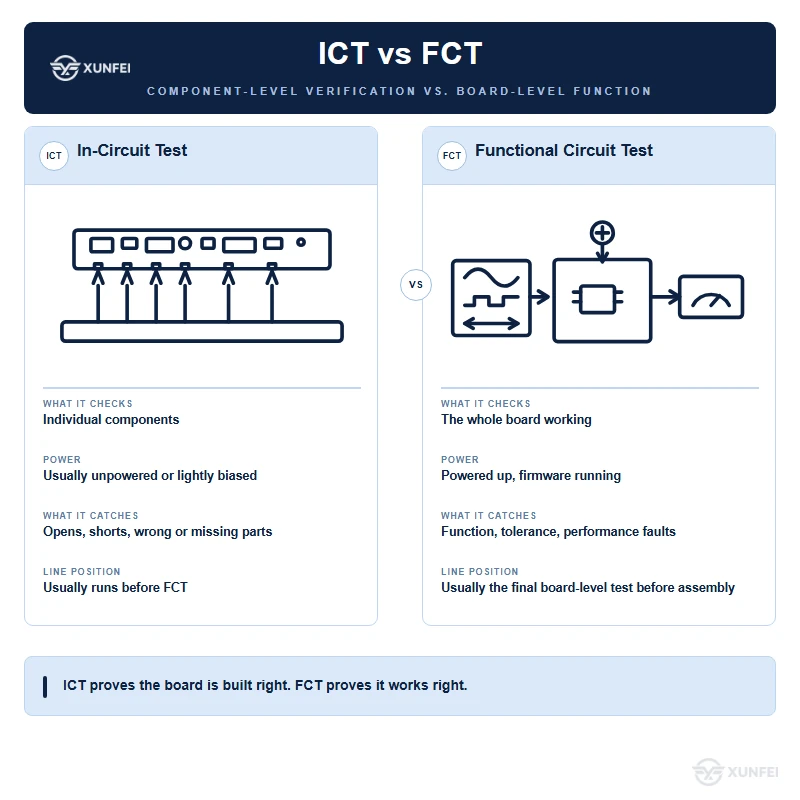
FCT and ICT are two different tests. ICT checks individual components and their values, one at a time. It catches wrong parts, reversed polarity, missing parts and open solder joints. FCT goes one step further. It treats the whole assembly as a single working product and checks whether the board does its job.
FCT is usually the final board-level electrical test before the board moves to final product assembly (box build). A board that fails here does not move on to the next process. That makes FCT a key quality checkpoint, not an optional extra step.
2. How Does FCT Work?
FCT treats the board as a finished product, not as a set of individual components. The test station powers up the board and applies real input signals. It then checks whether the outputs match the product specification. Most stations run an automated test program, so every board goes through exactly the same steps.
Think of it as a test drive for a car. Instead of measuring each spark plug and wire on its own, you turn the key, press the accelerator and see whether the car really moves and steers. FCT works the same way. It judges the board by overall behavior, not by single readings.
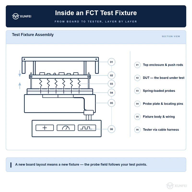
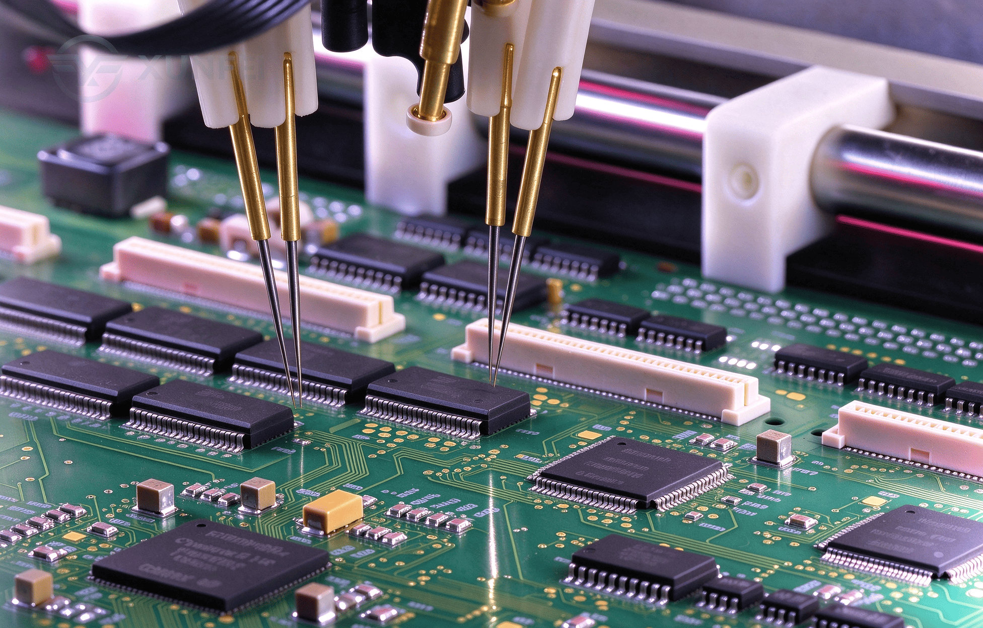
FCT needs a custom test fixture, also called a test jig or test nest, or a dedicated test station. The fixture holds the board in position and connects it to the tester through spring-loaded probes. The setup depends on the product functions, so a new design usually calls for a new fixture.
3. Typical FCT Test Items
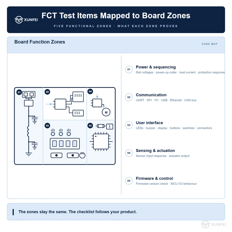
FCT covers many product-level checks. Typical items include:
-Power-up sequencing and the voltage on each power rail.
-Current consumption in idle and active modes.
-Communication interfaces: UART, SPI, I²C, USB, Ethernet and CAN bus.
-LED indicators, buzzers and displays.
-Sensor input response and actuator drive output.
-Firmware version check.
-Push-buttons, switches and connectors.
-Protection and fault-response behavior.
Test items depend on the product. A power board and a communication gateway need very different test coverage. That is why we build each test program around your schematic, firmware and acceptance criteria, not around a standard template.
4. FCT Applications and Test Time
Almost every PCBA runs FCT before it moves on to final product assembly. Common examples include consumer electronics, automotive modules, industrial gateways, medical devices and communication modules. Even a simple board usually gets at least a power-up and function check.
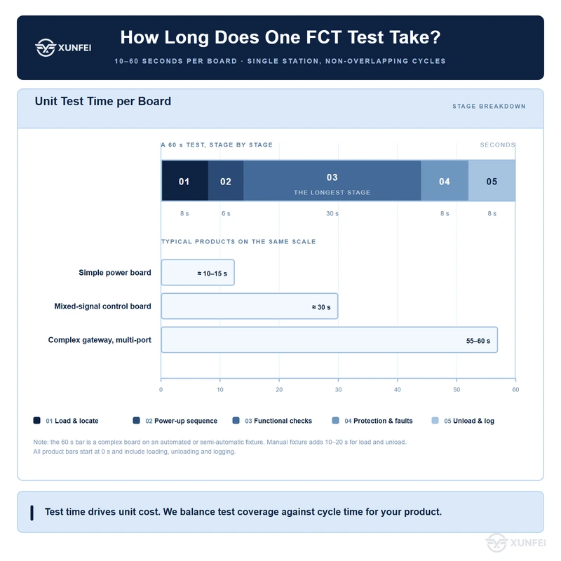
Typical test time is 10 to 60 seconds per board. The exact time depends on product complexity. A simple power board takes about 10 to 15 seconds. A complex gateway with several communication ports can take close to a minute. We always balance test coverage against cycle time, because test time directly drives your unit cost.
FCT is a full functional check, not a sampling test. Every board goes through FCT before it leaves the board line. The result is recorded under the board serial number, so every unit stays traceable.
5. FAQ
-How is FCT different from ICT?
ICT checks components one by one: value, polarity, presence or absence, and solder joints. FCT powers the whole board and runs its real firmware. ICT catches assembly faults. FCT catches faults that only show up when the board actually works.
-Do I need both ICT and FCT?
Usually yes. ICT finds faults early, while rework is still cheap. FCT confirms the board works as a product. Dropping ICT moves that work onto FCT and stretches the cycle time.
-How long does one FCT test take?
10 to 60 seconds per board. A simple power board takes 10 to 15 seconds. A complex gateway with several communication ports can take close to a minute.
-Do I need a new fixture when the design changes?
Usually yes, if the test points move. A layout change moves the probe field, so the probe plate has to be rebuilt. If only the firmware changes, the same fixture normally still works.
-What do you need from us to build an FCT program?
Send the schematic, the firmware, the test points and the acceptance criteria. We review them, quote the fixture and build the program. If the criteria are not defined yet, we propose them from the design.