ICT vs Flying Probe Test: Which Electrical Test Fits Your PCBA?
Release time:10/21/2026
Share to:
1. What Is ICT In-Circuit Test?
ICT means In-Circuit Test. It uses a bed-of-nails fixture, and probes make physical electrical contact with preset test points on the PCBA. During the test, ICT measures resistance, capacitance, inductance, diode forward voltage and transistor properties on every circuit node. In this way, it verifies correct component mounting and basic electrical performance.
As a fast electrical test, ICT checks many nodes at the same time. This makes it well suited to high-volume mass production. However, ICT does not check full product function. Instead, it checks individual components and circuit connections. That is the job of FCT.
1.2 How ICT Works ?
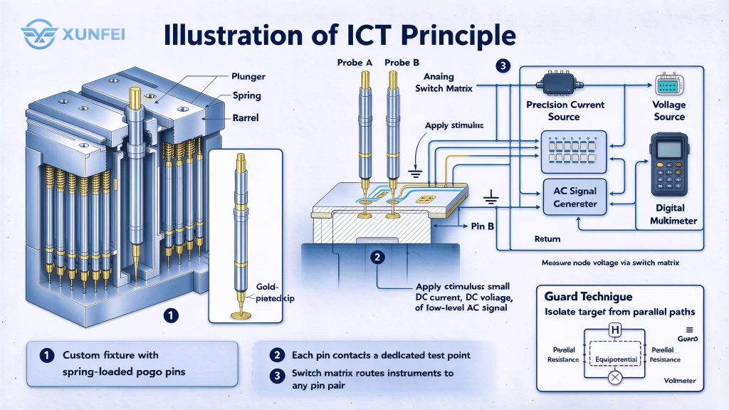
A custom fixture holds hundreds of spring-loaded pogo pins, each consisting of a plunger, a spring, and a barrel. The plunger tip is typically gold-plated to ensure low contact resistance.
Once all pins make contact, the test system begins its measurement sequence. It uses a matrix of analog switches to route internal instruments—precision current sources, voltage sources, AC signal generators, and digital multimeters-to any pair of pins. For each component under test, the system applies a known stimulus (a small DC current, a DC voltage, or a low-level AC signal) and measures the resulting voltage, current, or impedance.
Guard techniques are employed to isolate the target component from parallel paths in the surrounding circuitry, ensuring that the measurement reflects only the component of interest.
Because the pin layout is unique to each board design, a new fixture must be designed and machined for every product. Fixture fabrication involves precision drilling of the pin field, wiring of hundreds of coaxial or twisted-pair cables, and mechanical alignment verification. Typical fixture costs range from several thousand to tens of thousands of dollars, with lead times of one to three weeks.
For high-volume production, this investment is amortized over thousands of boards; for low-volume or rapidly changing designs, the cost and turnaround time become significant barriers.
1.3 ICT Detectable Defects
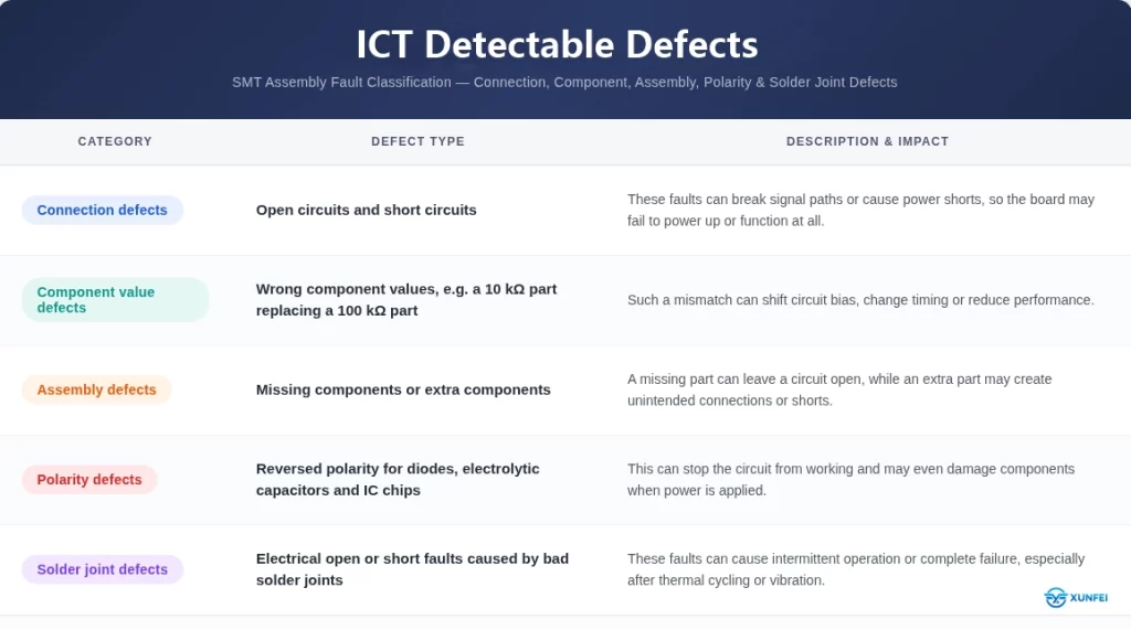
ICT can detect many electrical defects. These fall into several categories:
However, ICT cannot detect some defects. It cannot see solder voids, and it cannot check BGA joints reliably. That is why X-ray inspection is still needed.
1.4 ICT Applications and Test Time
ICT fits high-volume consumer electronics, automotive modules, industrial controllers and power boards. It also works well for products with accessible test points.
In terms of test time, a typical board takes 3-15 seconds. Thanks to its parallel pin architecture, ICT is the fastest electrical test method for mass production.Cost-wise, ICT is cost-effective when volume is high, because the fixture cost is spread across many boards.
2. What Is Flying Probe Test?
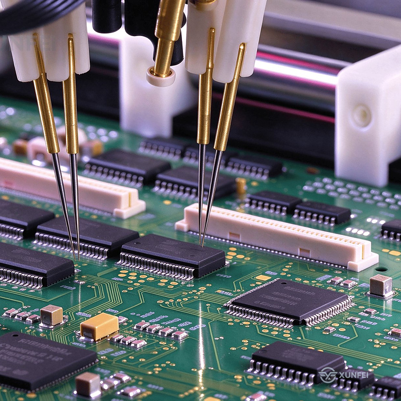
Flying probe testing is an electrical test method that uses multiple motor-driven, rapidly moving electrical probes to make contact with component pins and perform electrical measurements. Specifically, the Flying Probe Test utilizes 2 to 6 movable probes. These probes touch the test points sequentially, one by one. Unlike traditional methods, it does not require a custom-made bed-of-nails fixture. Despite this hardware difference, it performs the same electrical measurement items as standard In-Circuit Testing (ICT). What makes it highly versatile is its flexibility. Flying probe testing is well-suited for prototype samples and low-volume production, it easily accommodates design changes.
2.1. How Flying Probe Test Works?
Instead of a fixed pin bed, the flying probe test uses two to six precision probes mounted on programmable X-Y-Z arms. Each probe flies to a test point, touches down, takes a measurement, and then moves to the next point. The probes typically work in sequence, and some systems use several probes in parallel to shorten the test cycle.
The system is driven by a test program. The program defines the coordinates of each test point, the measurement type and the pass/fail limits. When the board is loaded and fixed in place, the probes move according to the program and measure one point after another. Optical or mechanical positioning helps the probes land on small pads accurately.
In this way, it works like a pianist who plays the keys one at a time with a single finger, rather than pressing all keys at once with both hands.Because no custom fixture is needed, there is no tooling cost, and program changes are quick. This is the main advantage.
2.2 Flying Probe Applications and Test Time
Flying probe fits R&D prototypes, small-batch industrial equipment, medical devices and aerospace boards. Choose flying probe when custom fixture investment makes no economic sense.
Typical test time is 30-120 seconds per board. Slower than ICT because probes must visit each point sequentially, but the trade-off is zero fixture cost.
3. ICT vs Flying Probe: How to Choose the Right Testing Method?
Flying probe test is flexible but slower, making it ideal for early production stages. In contrast, ICT is faster but requires a custom fixture, which makes it the backbone of high-volume manufacturing. Therefore, you should choose the right method based on your production volume and budget.
Item
ICT
Flying Probe
Fixture
Bed-of-nails fixture
Minimal or no fixture
Setup Time
Days
Minutes to Hours
Test Time
3-15 seconds per board
30-120+ seconds per board
Coverage
High (full node access)
High, but limited by test time
Cost per Board
Low
High
Fixture Cost
High
Very Low
Flexibility
Low (requires new fixture)
High (quick program changes)
In short, ICT wins on speed and coverage, securing the quality of mass production. Flying probe wins on flexibility and cost, enabling fast product development. Both play essential and complementary roles in the PCBA workflow.
4. FAQ
-What is ICT?
ICT means In-Circuit Test. It uses a bed-of-nails fixture to check components and circuit connections.
-What is flying probe test?
Flying probe testing is an electrical test method that uses multiple motor-driven, rapidly moving electrical probes to make contact with component pins and perform electrical measurements.
-What is the difference between ICT and flying probe?
ICT is faster and has higher coverage, but needs a custom fixture. Flying probe is slower but has zero fixture cost.
-How long does ICT take?
About 3-15 seconds per board.
-How long does flying probe take?
About 30-120 seconds per board.
-Can flying probe replace ICT?
No. Flying probe is slower and has lower coverage. It cannot replace ICT in high-volume production.Both play essential and complementary roles in the PCBA workflow.
Whether you need ICT or flying probe for rapid prototyping for mass production, XUNFEI offers one-stop services from PCB design and SMT to functional testing. Our self-owned factory delivers prototypes in 4-7 days with strict quality control using AOI and X-Ray. Contact us today for a free DFM review and exclusive quote to accelerate your time-to-market!